

Fit the site you have
Layout, utility connections and access are developed around your location and available power.
THE FACILITY FOUNDATION FOR DEPLOYABLE COMPUTE.
MODFLEX MODULAR DATA CENTERS
ModFlex brings the building, power and cooling together for AI and HPC. Start with the capacity you need, on the site you have, with a clear path to expand.
THE MODFLEX APPROACH
A purpose-built modular building system, not a fixed shipping-container catalogue. We bring the building, power, cooling and operating requirements into one facility design, with expansion planned from the start.

Layout, utility connections and access are developed around your location and available power.
Rack loads guide the power distribution, air or liquid cooling, and service access.
Plan the first deployment and the provisions for future growth before committing to the layout.
Plot constraints, utility connections, access, permitting inputs and the route from available power to usable IT capacity.
Load profile, resilience targets, distribution, protection, metering and planned growth considered as one electrical path.
Air, direct-liquid or hybrid cooling selected around actual rack loads, climate, water strategy and service requirements.
The first deployment and future physical, electrical and hydraulic provisions defined before the layout is fixed.
Service routes, controls, security boundaries and support spaces configured around the way the facility will be run.
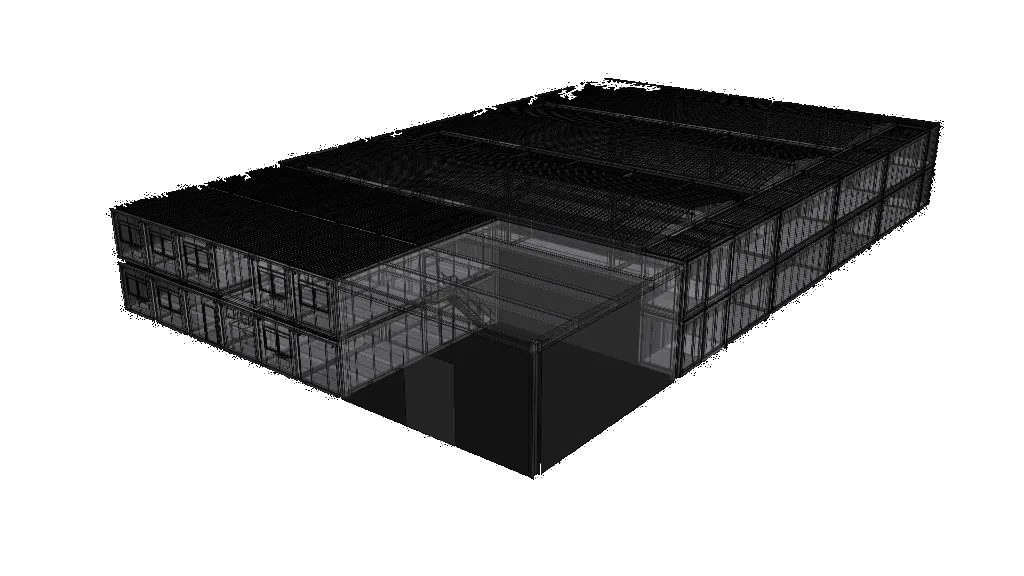
Steel-frame building modules developed around equipment loads, transport, assembly, durability and site requirements.
Rack halls, network and storage zones, electrical rooms, cooling plant, staging and operational spaces placed around the intended deployment.
External finishes, dimensions, circulation, security boundaries and surrounding infrastructure adapted to the location and planning context.
Defined growth stages let additional capacity follow demand, utility availability and commercial timing.
FROM FIRST CONVERSATION TO HANDOVER
Site work, engineering, manufacture and commissioning follow the same capacity plan. Scope, schedule and acceptance criteria are agreed for your project.
Confirm the site, power position, workload, target capacity, timeline, resilience objective and operating model.
Translate those inputs into module layout, capacity stages, rack assumptions, electrical architecture, cooling strategy and budget basis.
Coordinate structural, electrical, mechanical, controls and equipment packages against approved requirements and interfaces.
Progress module manufacture while site preparation, utility work and deployment logistics move forward in parallel.
Test systems, controls, failure responses and operating procedures against the agreed commissioning and acceptance plan.
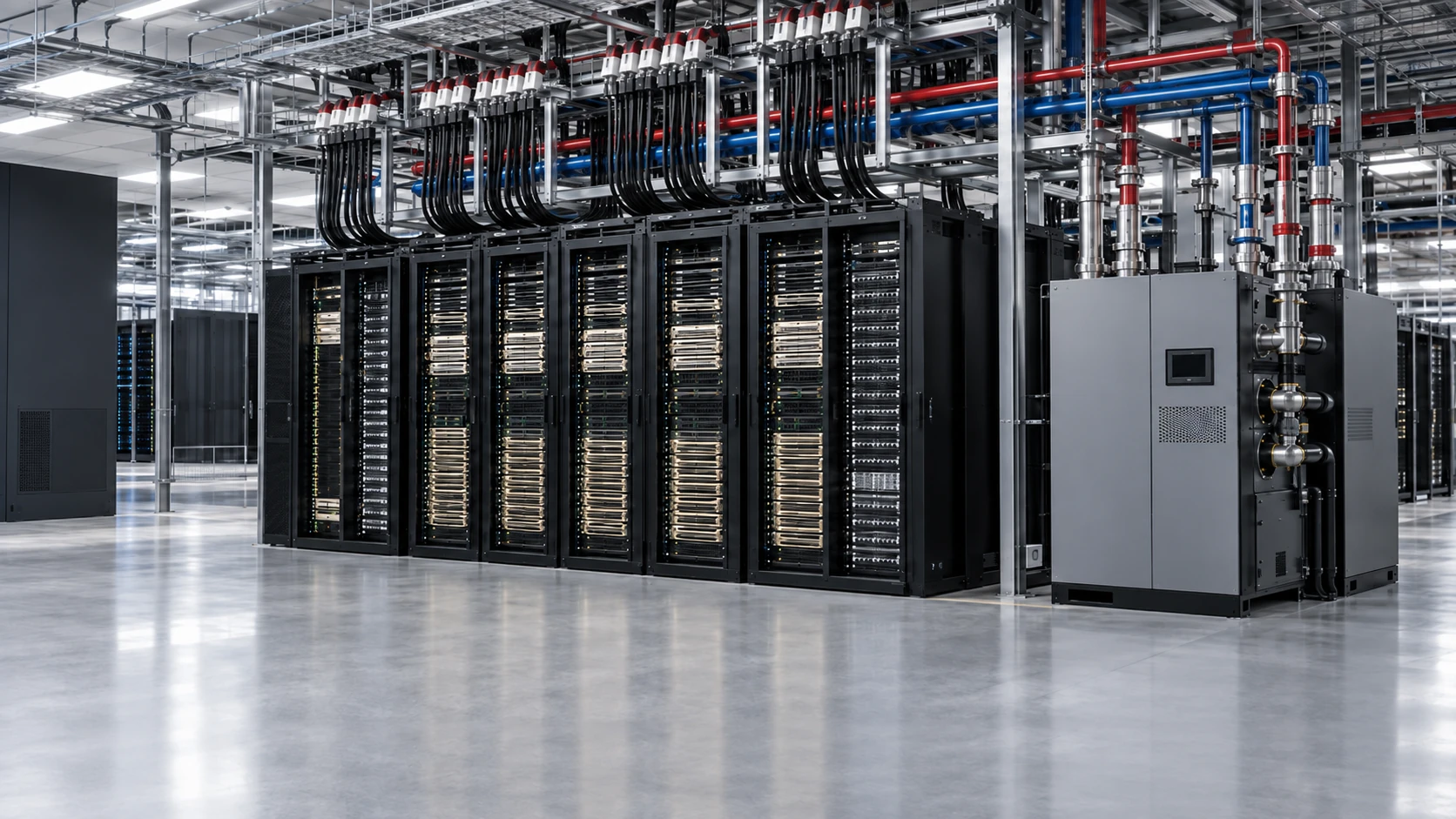
PLATFORM-AWARE FACILITY DESIGN
ModFlex can house your selected IT systems, or ElioVP can help integrate the compute, networking and storage. Facility design follows confirmed rack requirements; future platforms remain planning scenarios until their configurations are confirmed.
Explore AI infrastructurePlan around confirmed AMD MI355X, NVIDIA B300 and NVIDIA GB300 NVL72 system requirements and selected OEM rack data.
Model electrical, hydraulic, structural and spatial pathways for AMD Helios partner systems and NVIDIA Vera Rubin deployments, then confirm every assumption against the selected configuration.
Include fabric switches, storage systems, management networks, cable pathways, service clearances and supporting racks in the capacity model.
Redundancy, maintainability and failure-domain decisions follow the project’s operational requirement rather than a blanket claim.
Equipment replacement, isolation, maintenance routes, controls and safe working access are considered before the layout is fixed.
Electrical, mechanical, controls and operational scenarios are tested against a project-specific commissioning plan before handover.
ENGINEERING AND TRUST

Our engineering team includes a Uptime Institute Accredited Tier Specialist. That expertise informs decisions around resilience, availability and operations, but does not imply a project is Uptime Institute certified unless certification is separately scoped and achieved.
We respect our customers’ privacy and take sovereignty and operational security seriously. Many completed environments cannot be published publicly, but selected project photography, video and technical references may be shared privately with qualified organizations where customer permissions allow.
Request private project referencesLOOK INSIDE MODFLEX
Open the areas relevant to your project. These are separate illustrative configurations and studies, not one project specification or a guarantee of performance.
MODFLEX / INTERACTIVE EXPLORER
Fully modular, from the floor plan to the facade. AMD Helios is our flagship showcase. ModFlex can also be designed around NVIDIA and other AI, HPC or storage platforms, with the layout, systems and finish shaped around you.
The architecture shapes the space, too.
8 Helios · 6 storage · OOB
A few possibilities. Specify your own facade.
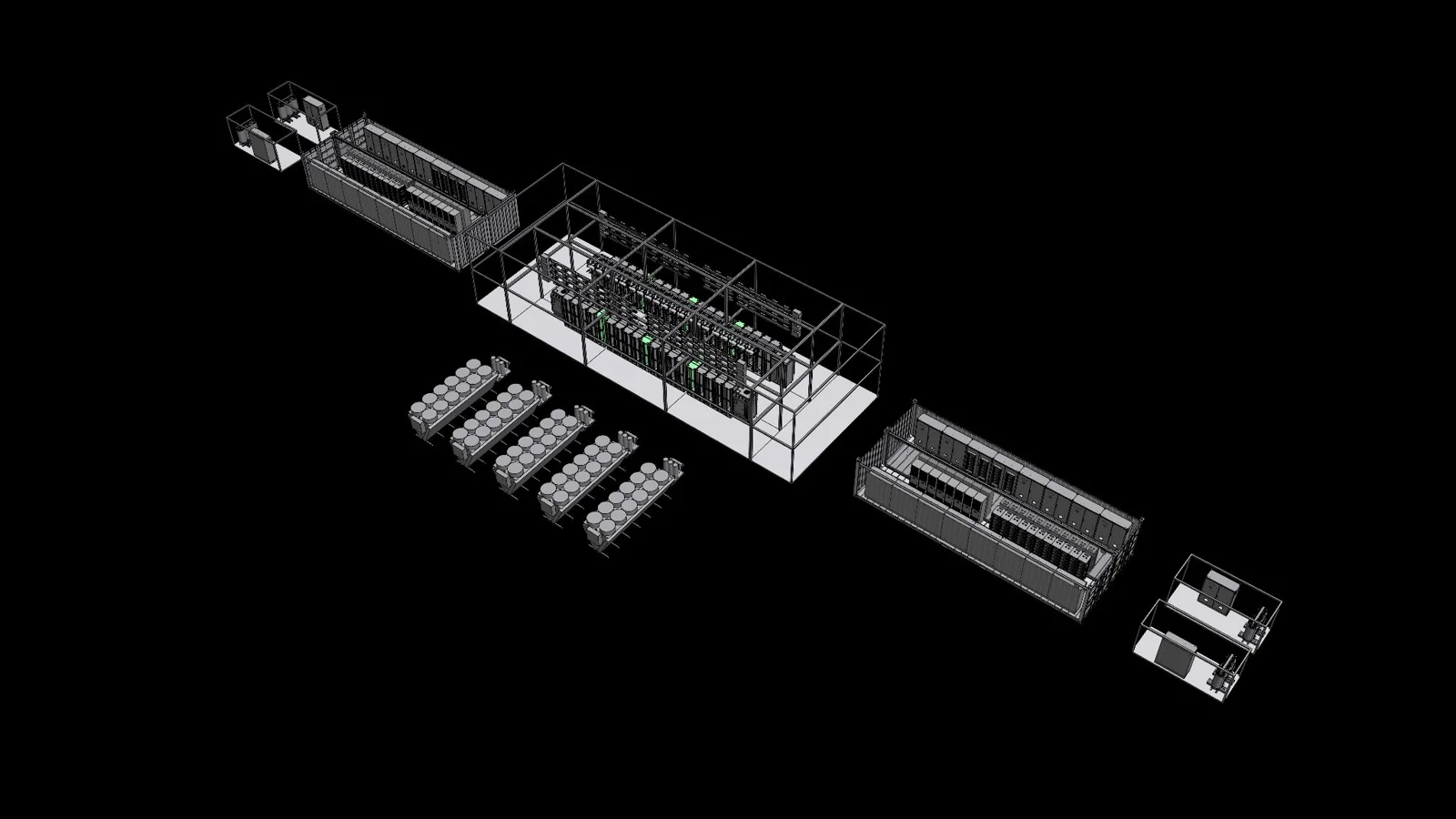
This is one possible configuration. Arrange the white space, Powerpods and cooling around your site and workloads. Choose the architecture, specify the finish and plan how you grow — with no fixed catalogue layout.
Flagship showcase: AMD Helios. ModFlex modules can be configured for other compute platforms. Layout, equipment, electrical sizing and cooling are tailored to each project. AMD Helios reference
Tell us how you want to build. We’ll shape the modules, exterior and infrastructure around you.
MODFLEX / AIRFLOW ENGINEERING
Good cooling design goes beyond choosing equipment. We use computational fluid dynamics (CFD) to examine how air moves through the room, where warmer air travels and how the layout shapes the result.
Compare the assumptions. Inspect the results. Document the design decisions.
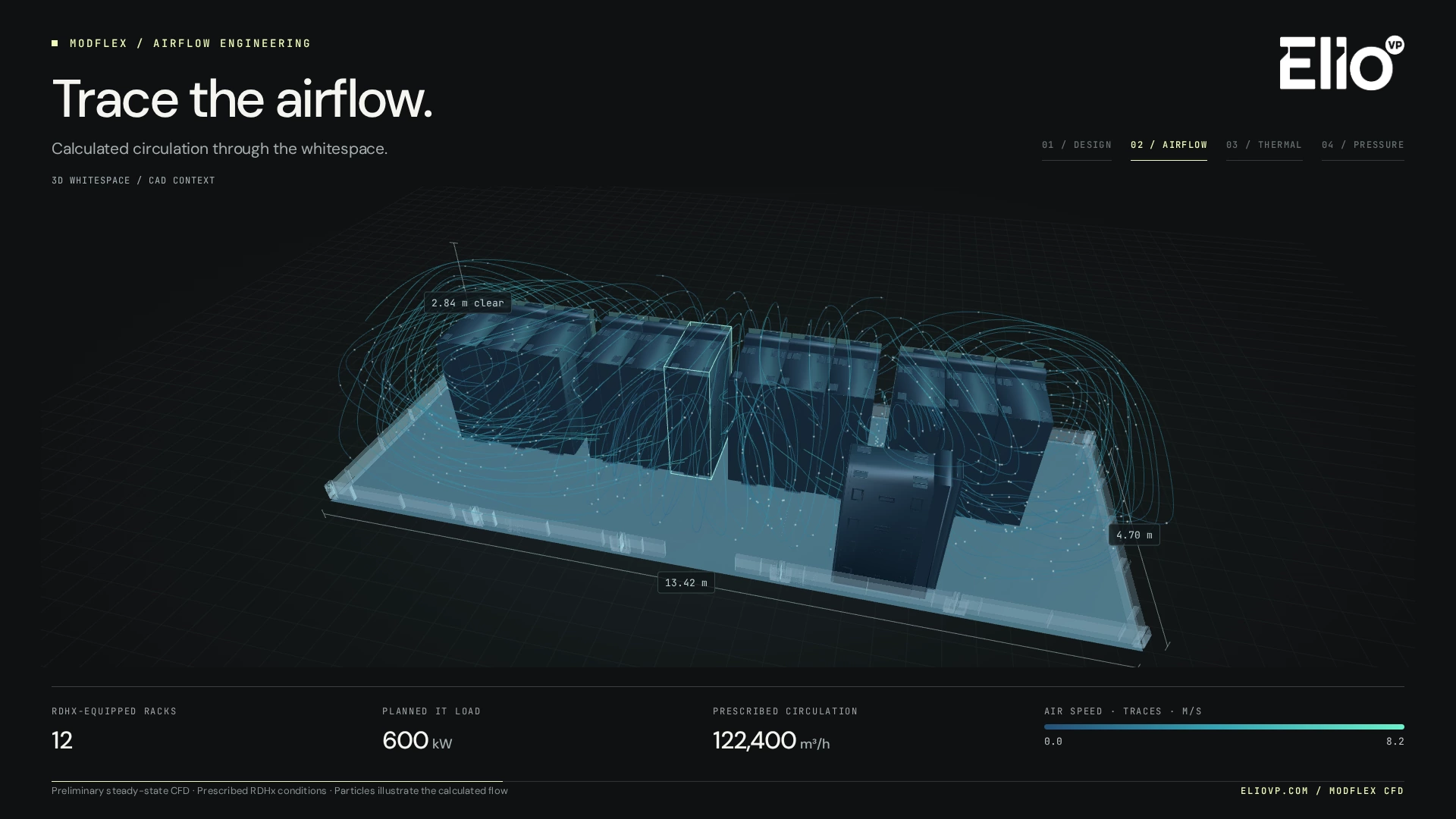
01AIRFLOW
Trace calculated circulation through the rack layout and rear-door heat exchangers (RDHx), with the room dimensions in view.
12 RDHx racks · 600 kW planned IT load
02TEMPERATURE
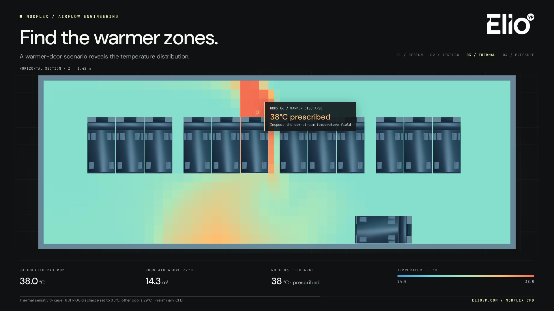
Set one rear-door discharge to 38°C and examine where warmer air travels. A deliberate sensitivity case, not a recorded equipment failure.
38°C prescribed input · 32°C review threshold
03PRESSURE
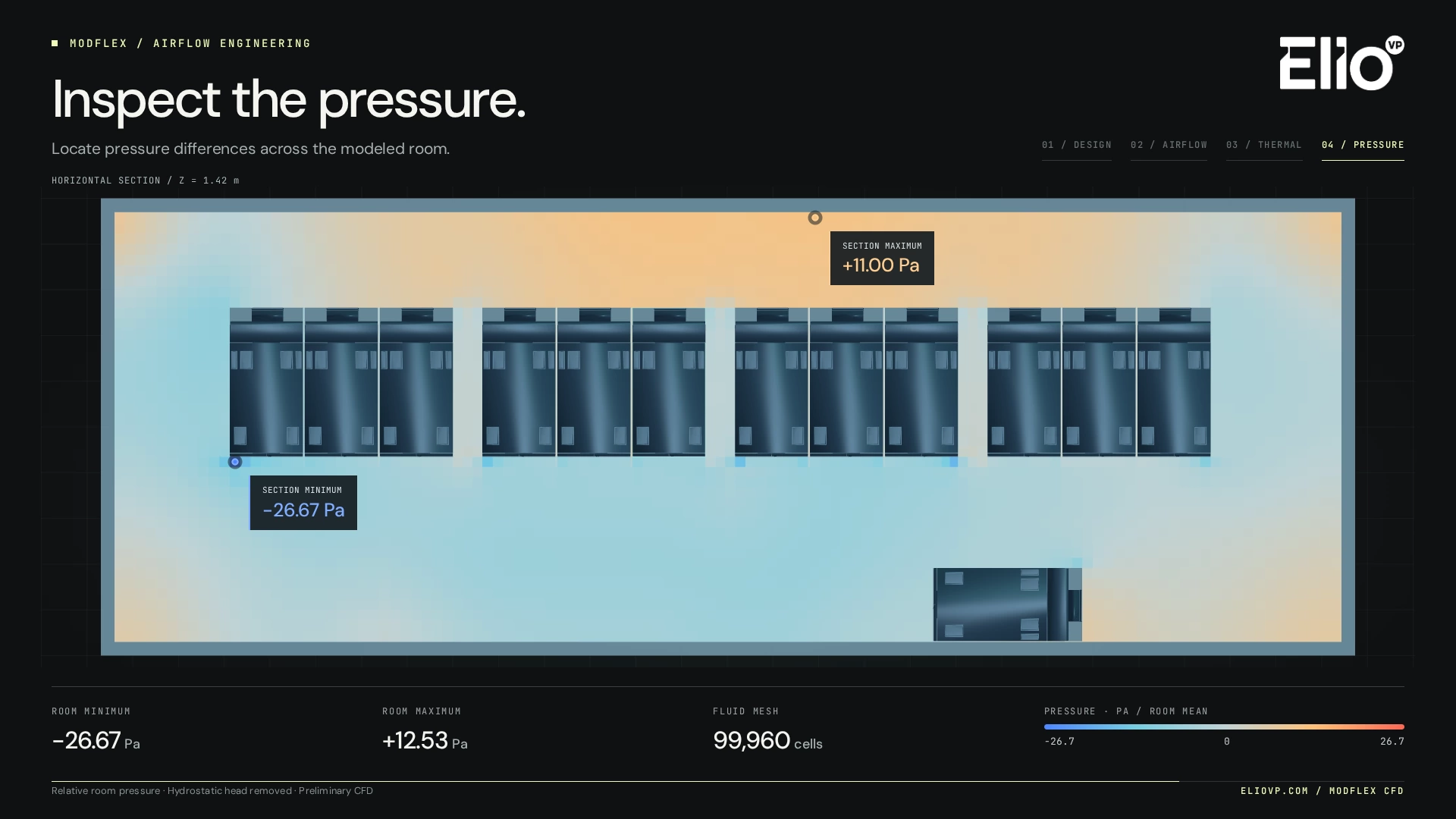
Examine calculated pressure differences across the room. Read each section against its legend and the defined scenario.
Relative room pressure, not fan pressure rise
The airflow and pressure study uses a 99,960-cell model of a 13.416 × 4.700 × 2.836 m room, with 12 RDHx racks, 600 kW planned IT load and 122,400 m³/h prescribed recirculation. These are scenario inputs, not a certified capacity rating.
The temperature study uses 9,480 cells, with RDHx 06 discharge prescribed at 38°C and the other doors at 29°C. The calculated maximum is 38.0°C; 14.3 m³ of room air exceeds that case’s 32°C review threshold. The discharge temperature is an input, not a predicted coil outlet temperature.
These are preliminary steady-state CFD results. Moving particles illustrate the solved velocity field, not a transient simulation. Pressure is relative to the volume-weighted room mean, with hydrostatic head removed. The results do not establish fan pressure rise, coil resistance, acoustics or validated cooling performance.
Bring your rack plan and operating assumptions. We can explore the scenarios that matter to your project and preserve the findings in an engineering report.
MODFLEX / INTERACTIVE RESILIENCE LAB
Cut the grid. Trip a pump. Take a power pod out of service. Explore how backup systems take over and how the remaining capacity responds, before a real failure ever happens.
Follow each change from the failed component to the rack. Try a prepared scenario, or build your own combination.
POWER / ONE MODFLEX BLOCK
Cut the grid and follow how UPS batteries bridge the load while generators start. Click a component to simulate a fault or restore it.
8 / 8 rack feeds available
150 kW requested
2.40 MW · Block IT load
1× · Simulation
Each scenario starts afresh with fully charged batteries.
Swipe sideways to explore the full diagram. Every component is also available under Advanced controls.
Generator + ATS · 10 s · 16 racks · 8 × 33 kW
At 150 kW, three paths carry the full rack load. With two paths, up to 132 kW per rack remains available.
The clock pauses automatically when this diagram is out of view.
Click to simulate a fault. Click again to restore the component.
Illustrative model, not live telemetry or an availability guarantee. 16 racks, 33 kW per power shelf, four independent paths and an assumed 10-second generator start. Actual performance depends on the build and project design.
Four CDUs, four pumps and four dry coolers share the load.
Swipe the diagram sideways. Click a CDU, pump or dry cooler to trip or restore it. The same controls are available below.
100% represents 1.92 MW of liquid-cooled heat. Adiabatic pre-cooling assists above 28 °C ambient.
Shared headers let the remaining three components in each family carry the illustrative design load. Click to trip or restore.
| Train | CDU | Facility pump | Dry cooler |
|---|---|---|---|
| A | |||
| B | |||
| C | |||
| D |
Illustrative concept inputs: 35/45 °C rack water, 30/40 °C facility water and 1.2 bar design pressure difference. Actual behaviour depends on the engineered installation, operating conditions and controls.
This example uses 16 GB300 NVL72 racks at 150 kW per rack: 2.40 MW of IT load, with a 1.92 MW liquid-cooling share. It is separate from the configurable 3D layouts above. It does not model every facility load or the remaining air-cooled heat.
Each path has a grid feed, generator, UPS, battery and busway, with two 33 kW power shelves per rack. The example generator start takes 10 seconds. Battery endurance varies with load; loss of multiple paths can force rack power capping.
Four CDUs, four facility pumps and four dry coolers serve shared headers. The design point is 25 °C ambient, with illustrative 35 °C rack-water supply and 1.2 bar rack differential pressure. Capacity depends on load, remaining equipment and ambient conditions; adiabatic assistance is assumed above 28 °C.
Transfer times, thermal inertia, temperatures and compute percentages are simplified concept assumptions. These are not live readings, a validated digital twin, a Tier certification or an availability promise. Every ModFlex project requires its own electrical, hydraulic, controls and commissioning studies.
Tell us your availability target, rack loads and maintenance requirements. We will define the right failure scenarios and commissioning plan for your site.
LET’S PLAN YOUR MODFLEX PROJECT
Share what you know so far. We will help turn it into a facility scope, capacity plan and practical next steps.